|
The
quasi-static design procedure given in most building codes are
ductility based and do not explicitly apply to buildings with
supplemental damping. In the past few years, several guidelines
on the analysis and design procedure of passive energy dissipation
devices have been developed in the U.S. The latest and most comprehensive
document is the "NEHRP Guidelines for the Seismic Rehabilitation
of Buildings, FEMA 356 / 357, issued in 2000".
The Guidelines require that the structure be evaluated for response
to two levels of ground shaking - a design basis earthquake (DBE)
and a maximum considered earthquake (MCE). The DBE is an event
with 10% probability of exceedance in 50 years, while the MCE
represents a severe ground motion of probability of 2% in 50 years.
Under the DBE, the structure is evaluated to ensure that the strength
demands on structural elements do not exceed their capacities
and that the drift in the structure is within the acceptable limits.
For the MCE, the structure is evaluated to determine the maximum
displacement and overstress. It is presumed that if proper ductile
detailing has been followed, the structure will have sufficient
reserve to avoid collapse during MCE.
Since different earthquake records, even of the
same intensity, give widely varying structural responses, results
obtained using a single record may not be conclusive. Therefore,
three time-history records, suitable for the region should be
used, one of which should be preferably site specific. The maximum
response is used for the design.
If seven or more earthquake records are used, the average response for design shoud be used.
NEHRP guidelines require that friction dampers
are designed for 130% MCE displacements and all bracing and connections
are designed for 130% of damper slip load. Variation in slip load
from design value should not be more that ± 15%.
Non-linear Time- History Dynamic
Analysis
The movement of damper in an elastic brace constitutes non-linearity.
Also, the amount of energy dissipation or equivalent structural
damping is proportional to the displacement. Therefore, non-linear
time-history dynamic analysis is a more accurate procedure for
the design of buildings with damping devices. With these analyses,
the time-history response of the structure during and after an
earthquake can be accurately understood.
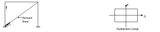
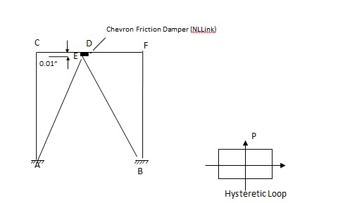
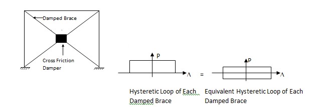
The modeling of friction dampers is very simple.
Since the hysteresis loop of the damper is similar to the rectangular
loop of an ideal elasto-plastic material, the slip load of the
friction damper can be considered as a fictitious yield force.
|